News and Events

Keep up to date with the latest news and events of Modular Bikes.

Saturday, July 6, 2019

Zzipper Fairing Part 3


Inside of bike trainer leg with crush bar

Shortening bike trainer wheels with pipe cutter with

this result. The trainer now suits the 20" bike wheel and means I get a realistic idea of the view over the fairing.  Struts supporting the bottom of the fairing are modified light steel tent pole tubes.
Glueing fibreglass rods into fairing support brackets. These rods help distribute stress into the parts which are home 3d printed.

Mounting bracket and...

fairing support.
A bucket from Bunnings and some handlebar ends from the shed.  Bits of the bucket are now the front of the fairing and the handlebar ends ...

fitted on the handlebars with white nylon bolts to hold the fairing top.
Using a holesaw set to make....

this small piece which covers a hole in the new, longer fairing. Without further modifying the fairing, I can mount a light to this wooden piece.

This set of fairing mounts didn't work as it placed the fairing support right near the pedals, causing interference.
End result after a quick test ride.  Still quite a few things to fix but I'm quite happy.
Another view, plan to go for a longer ride tomorrow.
Hi, this post is mostly pictorial again.  The fairing I received from OzHpv mates  5 or 6 weeks ago is now on a bike and ready for an 80k or so test ride tomorrow. The bike trainer I was using to test the fairing was for 700c bikes, and I cut it down to better sit a 20" and so I could get a realistic idea of my view of the road when testing.  The fairing mounting has been totally home made and the fairing has been extended using parts of a bucket.  Very happy with the results sofar. For a long time I have been aware that my front wheel drive bikes are an aerodynamic mess at the front, and this fairing should fix some of that.

Regards

Steve Nurse

Update, July 7: I took the trike for a ride of about 60k today (Mordialloc and back via beach road), with no real problems.  I had to stop a few times to do up screws which attach the fairing but that was to be expected as I hadn't bothered with nyloc nuts, spring washers etc.  I'm fairly out of condition and didn't stop to eat, drink or wee till I got back within a few k of home so was tired, thirsty and hungry when I got in.  Happy with the bikes speed and I overtook a few of the slower Beach road roadies. Didn't take many photos, and the ones I did take were undramatic and out of focus. Here is the best of them showing a screw coming undone!


Update, July 23: From here, the story goes sideways, I used the design of one of the fairing mounts for other purposes. Flick over to my design blog here for details. Trike is ready for a longer ride now, will report progress.  Regards  Steve Nurse

Monday, July 1, 2019

Gone Electric

Picking up trike from Rev-Bikes
Near my Mum and Dad's place, I visited them on the way home from picking up the trike. Original front wheel is in the back storage area.
Diagram showing the electric bits.

Handlebars, left to right: brake lever with sensor, throttle, bell, display, pedelec control, brake lever with sensor, gear changer (obscured)
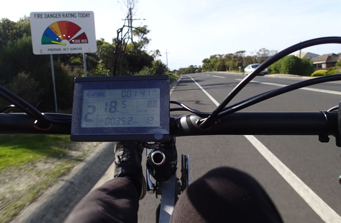
On the road: Midwinter and 12 degrees C so fire danger is low! Anyway, this is assist level 2,

and this is assist level 1, the minimum amount.
Shopping trip.....

in Anglesea.
Airies Inlet

Airies Inlet

Anglesea
Hi

After about 30 years making my own bikes run purely by human power, I have lashed out and had one of my trikes converted to electric motor assist.  The cost was about $1800, which I am justifying by considering this as being savings from decades of servicing my own cycles. Recently I have been writing an article about electric bikes for a conference and the time just felt right I guess.

Anyway, I asked around a bit and Nell from Wecycle works at Rev Ebikes, and Dale S from the Be-Spon ride group recommended them as well so after a discussion over the phone I dropped my trike at Rev the next day. Rev E-bikes are right next to Nunawading station, so it was easy to get there with my trike.

And 2 days later it was ready to pick up.  I rode it home from Nunawading and was impressed.  Basically you just set an assist level from 1 to 5 and the motor and controller combine to provide you with a corresponding level of assistance.  From riding on it a few times, level 1 gives you about 50w, 2 gives 100w, 3 150w etc.  I never really felt the need for more than level 3 of assistance, and used the motor  mostly up hills. Pedalling is usually required for electric assistance , so when the sensor on the bottom bracket knows you are pedalling and a power level is set at 1 - 5 the motor goes. The brake levers give a signal to the motor too, and when brakes are applied the motor cuts out.

The kit fits in well with my black bike steerer, and at first glance it might be hard to see the electric bits on the trike.  It fits in well with the bike's handling as well.  The basic drive design is very simple but it means you can't pedal while steering. But now you can electric motor!  Anyway, will report more a bit later.  Thanks to Rev-Becca, Chris and Chris for installing the kit.

Although this post mostly describes the electric kit, some readers might be new to this style of trike so here is a bit of recent background:

The trike was being modified to take a Zzipper fairing. To make the trike electric, I swapped the Zzipper trike out for another one, so the trike shown in this older post is now the electric trike.  But as well as removing any fairing paraphenalia, I swapped out the seat for  a new seat / tailbox combination. This post describes making the box, while this one describes finishing it off with some corflute panels and a corflute lid.

Moving forward, I feature the trike in this blog post which includes Cad pics by solar and electric car advocate, John Bird. John's pics include some proposed advanced version of the trike, and the link includes details of some research I wrote which includes my electric trike.

Regards

Steve Nurse

Corflute panels


Panel laid out with clip holders corflute cutouts. Panel was traced from the routed parts.
Using a soldering iron to spot-weld and drill corflute.  This makes small bridges that fold back clips can lock on to. See pics 7 and 8 for results.

After spot welding and drilling, cable ties are added to the bridges to secure them in place.

Lid Hinges Top

Lid Hinges below.  I put in a reinforcing plate.

Lid Hinge
Lid and corflute panels on a trike.

Inside the tailbox, showing the bridges and fold back clips
Lid retainer, these are hair ties or hair elastics from Lyncraft.
Recent donation to Wecycle, a Peugeot Mixte and

a fairly anonymous clunker I worked on.
Corflute tailbox in action.


Hi,

This post continues on from the recent one about Spacetank where I made a tailbox.  The kit for the box includes plywood panels but while they are very robust, they are a bit heavy.  Never fear!  The panels are held in place by fold back clips and can be replaced by whatever you like.  So the photos show making corflute tailbox sidepanels and a corflute tailbox lid.

Like the Spacetank post, this is reasonably thorough, and out of this build I will be able to document how to make them.  I've included a couple of bikes that are making there way through Wecycle.  I volunteer there Saturday mornings and its a fun way to fix bikes and hang out with nice people.

Regards

Steve Nurse